
G SERIES SOLAR COLLECTORS
TECHNICAL SPECIFICATIONS
G Series Solar Collector - Model G32-P

SRCC OG-100 Certified
Certification # 100-2006005A
TECHNICAL SPECIFICATIONS
G Series Solar Collector - Model G32-P
SRCC OG-100 Certified
Certification # 100-2006005A
Directory
-
General Information
- Product description
- Product Use
- Manufacturer's Experience
-
Glazing System
- General Description
- Optical Performance
- Structural Performance
- Thermal Performance
- Fire Behavior
- Durability
-
Absorber System
- General Description
- Optical Performance
- Thermal Performance
- Mechanical Integrity
- Durability
-
Insulation
- General Description
- Thermal Performance
- Fire Behavior
- Durability
-
Collector Assembly
- General Description
- Collector Container
- Moisture Control
- System Sealant and Gaskets
-
Installation
- Handling and Transportation
- Mounting Procedure
- Collector Interconnection
- System Connection
- Start-up Tests
-
Operation
- Method of Operation and Control
- Pressure Drop vs Collector Flow
- Recommended Flow Rate
- Maximum Operating Pressure
- Recommended Operating Pressure
- Maximum Operating Temperature
- Stagnation Temperature
- Recommended Heat Transfer Fluids
-
Maintenance and Warranty
- Cleaning and Maintenance
- Manufacturer Servicing
- Availability of Parts
- Replacement of Parts
- Warranty
-
Durability
- Operating Experience
- Accelerated Aging Tests
-
Collector Efficiency
- General Description
- Test Conditions
- Time Constant
- Efficiency
- Incident Angle Modifier
- FSEC Standard Day Tests
Download G Series Technical Specifications
A. General Information
1.0 Product Description:
-
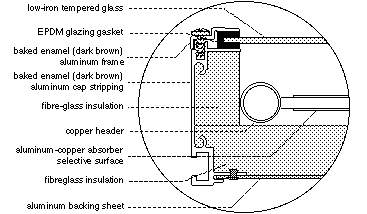
Thermo Dynamics G Series flat plate liquid collectors are single glazed with low-iron tempered glass. The absorber is an arrangement of parallel riser fins connected to top and bottom headers. The fins are aluminum with integral copper riser tubes, which are completely surrounded by the aluminum and are metallurgically bonded together. The copper riser tubes are soldered to internal manifolds (headers), which are available in either 3/4" or 1" diameter copper pipe. The back and sides are insulated with a 25 mm (1") layer of compressed fiberglass. The collector frame is extruded aluminum with a baked-enamel finish, (dark brown). Collector mounting is by way of a sliding bolt-track. Flush and racked collector mounting formats are easily accommodated.
1.1 Options
- Factory installed temperature sensors; 3/4" and 1" headers; 12 mm (1/2") riser tubes; absorber coatings: selective paint surface.
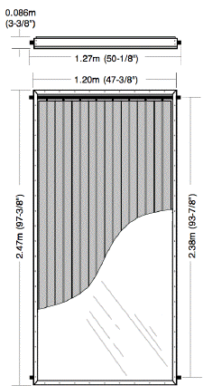
1.2 Dimensions and Volumes
- 1.20 m x 2.475 m x 0.086 m
- (47-3/8 in x 97-3/8 in x 3-3/8 in)
- Gross area: 2.982 m2 (32.10 ft2)
- Aperture area: 2.783 m2 (29.96 ft2)
- Absorber area: 2.870 m2 (30.90 ft2)
- Volume (19 mm (3/4") header): 2.3 liter (0.51 IG) Volume (25 mm (1") header): 3.0 liter (0.66 IG)
1.3 Weight:
-
Net: 43.5 kg (96 lb)
- Shipping: 64 kg (140 lb)
- (includes wooden crate)
2.0 Product Use
2.1 Product Applications:
- Residential and commercial domestic hot water, process hot water, space heating, pool heating
2.2 Geographic and Climatic Limitations:
- None.
-
Solar Rating & Certification Corporation (SRCC) #100-2006-005A
Listed by Natural Resources Canada (NRCan) as an accepted solar collector
- 3.0 Manufacturer's Experience
3.1 Background
- Thermo Dynamics Ltd. (TDL) is a Canadian company engaged in the research, development, production, distribution and installation of solar thermal equipment. The company has been involved in the solar thermal industry since 1981 and operates from its head office and factory in Dartmouth, Nova Scotia, Canada, the sister city of Halifax situated on the Atlantic coast. The company's specialization is the glazed liquid-flat-plate (LFP) collectors with metal absorbers. TDL is a fully integrated solar thermal company with the ability to convert raw aluminum and copper into a high technology solar water heating system.
- Thermo Dynamics Ltd., as a world leader in solar technology, manufactures and markets solar heating equipment from complete systems to basic selective surface components for O.E.M.'s licensees, dealers and distributors through out North America, Europe, Africa, New Zealand, as well as 10 other countries around the world.
3.2 Production:
- 3000 m2 per year for G32 collectors.
3.3 Projects:
- Mount Saint Vincent Motherhouse, Halifax, Nova Scotia, Canada. Largest SDHW system in Canada. Collector type and number: 224 - G32 Collector area: 675 m2 (7,265 ft2) 1.75 GJ/m2 /year (154 MBtus/ft2 /year)
-
Top of the Mountain Apartments, Halifax, Nova Scotia, Canada. Collector type and number: 49 - G32; 49 - G40 Collector area: 328 m2 (3,531 ft2) 1.78 GJ/m2 /year (156 MBtus/ft2 /year)
-
Somerset Place Apartments, Halifax, Nova Scotia, Canada Collector type and number: 120 - G32 Collector area: 356 m2 (3,332 ft2) 2.10 GJ/m2 /year (185 MBtus/ft2 /year)
-
Thermo Dynamics Ltd. has installed thousands of solar residential domestic hot water and pool heating systems.
B. Glazing System
1.0 General Description:
- Glazing is a 3.2 mm (1/8") single sheet of low-iron tempered glass with an EPDM rubber seal around the edges. Glazing is secured by an aluminum capping fastened by stainless steel screws around the perimeter.
1.1 Trade Names:
- Solite
1.2 Chemical Composition:
- Iron oxide content of 0.03%
1.3 Physical Treatment:
- All glazing is tempered with swiped edges and has a shallow stipple pattern to reduce specular reflectance.
1.4 Thickness:
- 3.18 mm (1/8")
1.5 Spacing:
- Glazing to absorber: 20 to 25 mm (3/4" to 1")
1.6 Weight:
- 7.8 kg/m2 (1.6 lb/ft2)
1.7 Appearance:
- Translucent; the inner surface is embossed with a stipple pattern which produces a frosted effect.
2.0 Optical Performance
2.1 Spectral Transmittance:
- Visible light 89.8% ASTM E424-71A Ultra violet light 51% ISO 9050 Solar light/energy 89.5% ASTM E424-71A
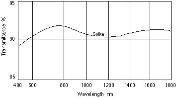
2.2 Energy Transmission:
- Solar spectrum (0-3 micrometres) 89.5% Infrared spectrum (>3 micrometres) No data available
2.3 Refractive Index:
- 1.525
3.0 Structural Performance
3.1 Tensile Strength:
- Design Pressure is 2.87 kPa (.416 psi) for 1/8 inch glass with a design factor of 2.5. Tensile strength is 152 MPa (22,000 psi) with a 2.5 safety factor.
3.2 Impact Resistance:
- Glazing can withstand 542 J (400 ft-lb) soft-body impact, 3 to 5 times stronger than annealed glass.
3.3 Uniform Load Resistance:
- Uniform load testing was conducted at the National Solar Test Facility in January 2007as part of CSA-F378-87.
-
Positive load: 1.5 kPa (0.22 psi)
- Negative load: 1.9 kPa (0.28 psi)
4.0 Thermal Performance
4.1 Coefficient of Thermal Expansion:
- 89.9 x 10⁻⁷ 1/°C (49.9 x 10⁻⁷ 1/°F)
4.2 Operating Temperature Range:
- Min: below -46°C (-51°F); max: 260°C (500°F)
4.3 Thermal Conductivity:
- No data available
5.0 Fire Behavior:
- Non-combustible. Does not produce toxic fumes in a fire situation.
6.0 Durability:
- Glass is chemically inert to most chemical solvents and staining agents, and is resistant to surface weathering, ultraviolet and thermal degradation, and moisture damage.
C. Absorber System
1.0 General Description:
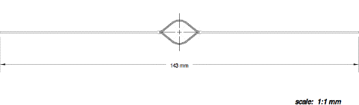
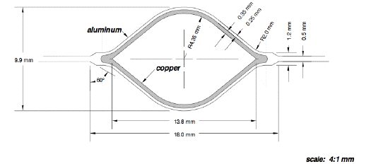
- The absorber consists of eight parallel aluminum fins with integral copper riser tubes, which are bonded to and completely surrounded by the aluminum by means of high-pressure cold-rolling process. The absorber coating is Anodic-Cobalt selective surface or black paint selective surface. The riser/header connection has two parts, a short copper nipple brazed to the header with the absorber fin soldered to the copper nipple.
1.1 Generic/Trade Names:
-
Absorber fins: "Sunstrip"
- Tubes: copper
- Headers: Type M copper
- Coating: SOLEC
- Solder/Brazing: 95/5 tin antimony/Silfos
1.2 Chemical Composition:
-
Absorber fins: aluminum (AA 1350/0 alloy)
- Tubes: copper (CDA 1220/0 alloy)
- Headers: copper
- Coating: selective black paint paint
- Solder/Brazing: no data available
1.3 Physical Treatment:
- None.
1.4 Dimensions:
-
Tube diameter: rhombic shape with an open area of about 120 mm2 (0.19
in2 )
- Tube spacing: 143 mm (5.63")
- Header diameter: 22.2 or 28.6 mm (3/4" or 1") nominal
- Absorber thickness: 0.5 mm (0.02")
- Coating thickness: no data available.
2.0 Optical Performance
2.1 Absorptivity of Solar Radiation:
- Painted surface: a = 95%
2.2 Emissivity of Infrared Radiation:
Painted surface: e = 25%
3.0 Thermal Performance
3.1 Thermal Transfer:
- Good thermal transfer due to the high conductivity of aluminum and the bond between the aluminum fins and copper tubes.
3.2 Coefficient of Thermal Expansion:
-
Absorber: no data available
- Tubes: no data available
- To allow for thermal expansion, the absorber is free to float within the collector container. EPDM gaskets prevent contact between the copper headers and the aluminum container.
3.3 Thermal Capacity of Absorber System:
- No data available.
3.4 Operating Temperature Range:
-
Absorber: max. 160°C (320°F)
- Tubes: max. 160°C (320°F)
- Solder/Brazing: min. -50°C (-58°F); max. 160°C (320°F)
- Coating: max. 160°C (320°F)
4.0 Exposure Test:
- The collector has completed a 30-day outdoor no-flow exposure test at The National Solar Test Facility (NSTF), Mississauga, Canada, June 2006. The test was in accordance to CAN/CSA F378-87. The test includes a preconditioning rain penetration test, 30 days exposure with a minimum of 17 MJ (16 MBtu) of incident energy per square metre of collector surface area, and a cold fill (thermal shock) test. There was no sign of degradation or loss in performance.
5.0 Durability:
- The absorber and the selective surface are not affected by normal aqueous solutions. Stagnation testing has shown no thermal degradation.
D. Insulation
1.0 General Description:
- Collectors are insulated around the sides and back with fiberglass board. Complies with ASTM-C-612 Classes 1 and 2.
1.1 Trade Names:
-
Sides: Fiberglas AF530
- Back: Fiberglas AF530
1.2 Chemical Composition:
- Fibrous glass bonded by a thermosetting resin. Inorganic, will not rot.
1.3 Density:
- 48 kg/m3 (3.0 lb/ft3)
1.4 Thickness:
-
Side: 25 mm (1")
- Back: 25 mm (1")
2.0 Thermal Performance
2.1 Thermal Conductivity:
- 0.036 W/m·°C (0.25 Btu ·in/hr·ft2·°F) at 24°C (75°F)
2.2 Thermal Resistance:
- RSI 0.7 °C·m2/W (R 4 °F·ft2·hr/Btu) at 24°C (75°F)
2.3 Coefficient of Thermal Expansion:
- No data available
2.4 Operating Temperature Range:
- Maximum continuous operating temperature is 232°C (450°F).
3.0 Fire Behavior
3.1 Surface Burning Characteristics:
- Fiberglas AF530 is inherently fire safe. ULC Flame Spread rating of 15. (compared to untreated Red Oak as 100 - test method ULC S-102)
4.0 Durability:
- No changes should occur to the insulation when subjected to chemicals normally encountered in use conditions. No thermal degradation has been found after prolonged stagnation testing. Moisture adsorption is less than 0.2% by volume, 96 hours at 49°C (120°F) and 95% R.H. Inorganic therefore does not breed or promote bacteria and fungus. Essentially odorless.
E. Collector Assembly
1.0 General Description:
- The collector is assembled in four stages. First, the collector frame and backing sheet are assembled. Second, the back and side insulation are installed. Third, the tested absorber assembly is inserted, and finally, the glazing, seal and cap are installed.
1.1 Container:
- The container consists of sections of aluminum extrusion assembled into a rectangular frame, with an aluminum backing sheet fitted into slots and pop-riveted in place.
1.2 Insulation:
- Insulation is placed on the aluminum back and along the sides.
1.3 Absorber Assembly:
- The pre-assembled absorber is fitted into the insulated container with the inlet and outlet connection pipes protruding through the sides. A high-temperature EPDM gasket is then fitted onto the pipes and locked into the aluminum frame. The absorber is free to expand or contract inside the container.
1.4 Glazing Assembly:
- The pre-cut glass is cleaned and fitted onto the retainer ledge in the collector container with a high-temperature continuous EPDM gasket. A removable aluminum cap stripping is then secured to the container with black oxide coated stainless steel screws.
2.0 Collector Container:
- Collector container sides are fabricated from aluminum extrusions with an integral mounting channel. The bottom is an aluminum sheet which fits into a slot in the frame and is pop-riveted to the sides.
2.1 Materials:
- Extruded framework is aluminum 6061-T6 alloy. The back sheet is aluminum utility grade sheet with a thickness of 0.51 mm (.020")
2.2 Finish:
- Aluminum frame comes in a standard dark brown baked enamel finish.
3.0 Moisture Control System:
- Four holes in the back sheet allow sufficient air flow through the collector to remove any condensation or moisture.
4.0 Sealant and Gaskets
4.1 General Description:
- Inlet and outlet pipes are sealed with high-temperature round EPDM gaskets. The continuous glazing gasket is a U-shaped EPDM neoprene. Silicone caulking is used for the container corner sealant.
4.2 Chemical Composition:
- Header and glazing gasket: ethylene propylene diene monomer rubber (EPDM) Caulking: silicone rubber
4.3 Physical Properties:
- EPDM gasket has a tensile strength of 13800 kPa (2000 psi). Sealants and gaskets do not corrode other collector materials.
4.4 Coefficient of Thermal Expansion:
- no data available.
4.5 Operating Ranges:
- no data available.
F. Installation
1.0 Handling and Transportation
1.1 Packaging:
- Collectors are shipped individually in double-strength cardboard boxes.
1.2 Labour and Equipment:
- Two people can move and mount collectors.
2.0 Mounting Procedure:
- Collector mounting channel allows precise spacing between collectors. Two adjacent collectors can be fastened to the sub-structure using bolts positioned anywhere along the bolt track in the collector frame.
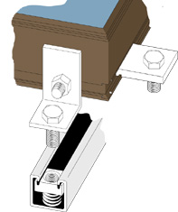
3.0 Collector Interconnection:
- Connection of up to four collectors in a single array. Collectors use standard copper couplings sweat-soldered with 95/5 solder to connect the internal manifolds of adjacent collectors.
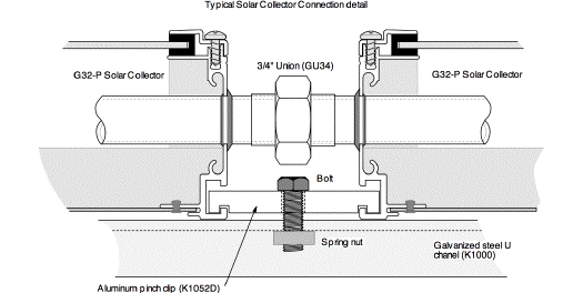
4.0 System Connection:
- Piping connections are sweat-soldered to the ends of the collector arrays using standard plumbing fittings.
5.0 Start-up Tests:
-
i) Air or water pressure test.
- ii) Visual check for leaks.
G. Operation
1.0 Method of operation and Control:
- Collectors can be used in closed or open loop systems with water or antifreeze.
2.0 Pressure Drop vs. Collector Flow:
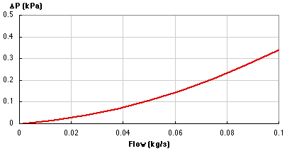
2.1 Testing Information: Agency:
-
Agency: Bodycote Testing Group
- Date: January 18, 2007
- Fluid: water
3.0 Recommended Flow Rate:
- 0.8 to 1.5 L/min (0.18 to 0.33 IGPM)
4.0 Maximum Operating Pressure:
- Factory tested to 1724 kPa (250 psi).
5.0 Recommended Operating Pressure:
- Below 200 kPa (30 psi) for drainback systems and 135-270 kPa (20-40 psi) for closed loop systems.
6.0 Maximum Operating Temperature:
- 200°C (392°F)
7.0 Stagnation Temperature:
- Stagnation temperature of the collector is approximately 170°C (338°F).
8.0 Recommended Heat Transfer Fluids:
- Propylene glycol USP, food grade antifreeze solution for closed loop systems, and water for drainback and seasonal pool systems. The use of inhibited glycols is not recommended. DO NOT use ethylene glycol.
H. Maintenance and Warranty
1.0 Cleaning and Maintenance:
- Glazing should be self-cleaning, depending on local conditions. Dirt accumulation on the glass cover will be washed away by the rain. If cleaning is required, use a standard window cleaning agent. The glycol antifreeze solution should be checked annually and renewed if necessary. No other maintenance is normally required.
2.0 Manufacturer Servicing:
- A trouble-shooting guide to help the home-owner maintain and service the equipment is included in the installation manual. All service and repair is readily available from the manufacturer or distributor.
3.0 Availability of Parts:
- All parts are available from the manufacturer and distributors.
4.0 Replacement of Parts:
- The glazing may be replaced in the installed system without removing the collector from the array by removing the screws holding the glazing cap stripping. Total replacement time is a maximum of fifteen minutes and requires only a screw driver. Sensors are clamped on outlet piping using screw-type pipe clamps. Replacement time is approximately ten minutes. If the recommended installation procedures are followed, one collector may be replaced in the array without removing another collector. Collectors are connected together with a standard copper couplings (mechanical or soldered).
5.0 Warranty:
- The solar collector absorber is warranted for a period of ten years. Repair allowances may also apply. The manufacturer may repair or replace the absorber as required at his discretion.
I. Durability
1.0 Operating Experience:
- The G32 has been installed worldwide since 1985.
2.0 Accelerated Aging Tests:
- The collector has been subjected to 30 day plus high temperature (204°C;400°F) stagnation tests at the Canadian National Solar Test Facility with no evidence of deterioration (CSA F-378). One year of stagnation at DSET laboratories in Arizona were also conducted in 1982 with no sign of deterioration.
J. Collector Efficiency
1.0 General Description
1.1 Test Method:
- Tested in accordance with SRCC (Solar Rating and Certification Corporation) Standard OG100-05, "Test Methods and Minimum Standards for Certifying Solar Collectors" with reference to ANSI/ASHRAE Standard 93.
1.2 Testing Information:
-
Agency: Bodycote Testing Group
- Location: Ontario, Canada
- Lat. 43.53 °N Long. 79.66 °W
- Elevation: 160 m (525 ft)
- Date: January 18, 2007
1.3 Details of Tested collector:
-
Model: G32-P
- Glazing: low-iron tempered Solite
- Absorber material: aluminum fin and tube
- Absorber coating: SOLEC black paint
- Insulation: fiberglass
- Gross area: 2.982 m2 (32.10 ft2)
- Aperture area: 2.783 m2 (29.96 ft2)
- Absorber area: 2.870 m2 (30.89 ft2)
1.4 Comments:
- The time constant, thermal efficiency and Incident Angle Modifier were determined in the solar simulator.
2.0 Test Conditions
2.1 Collector Tilt and Orientation:
- Normal to the direction of irradiation.
2.2 Heat Transfer Fluid:
- Water
2.3 Liquid Flow Rate:
- 0.059 kg/s (0.13 lb/s)
2.4 Mean Ambient Air Temperature:
- 20.3°C (68.5°F)
2.5 Wind Velocity:
- 3.2 m/sec (10.5 ft/sec)
2.6 Range of insolation:
- 808 W/m2 (256 Btu/ft2 h)
3.0 Time Constant:
-
95 sec at 0.059 kg/s (0.139 lb/s) water
Inlet temperature: 22.8°C (73.0°F)
Ambient temperature: 20.1 (68.2°F)
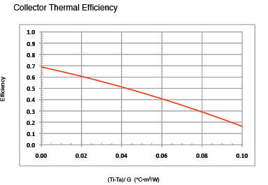
4.0 Efficiency:
Efficiency curve is based on gross collector area, and was determined using the indoor solar simulator. First order efficiency equation:
-
1st order: eff = 0.700 - 4.933(Ti - Ta)/G
- 2nd order: eff = 0.689 - 3.8475(Ti - Ta)/G - 0.01739(Ti - Ta)^2/G
-
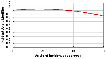
5.0 Incident Angle Modifier:
K(ta) = 1 - 0.154(1/cosq - 1)
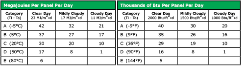
6.0 FSEC Standard Day Tests:
- The following standard day tests were performed by The Florida Solar Energy Center, (FSEC).
The G Series Collectors described by this brochure, when properly installed and maintained, meet the minimum standards established by the SRCC, (Solar Rating & Certification Corporation). This certification does not imply endorsement or warranty of this product by SRCC.
home | about us | solar collectors | solar systems | solar pumps | solar radiant floor heat |solar pool heat | solar fins | heat exchangers | project & photo gallery | technical specifications | downloads | product list | contact us
© 1996 - 2010, Thermo Dynamics Ltd.
All Rights Reserved
webmaster@thermo-dynamics.com
