
Thermo Dynamics Ltd.
State of the Art Production Facility
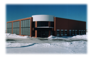
In November 2002, Thermo Dynamics Ltd. (TDL) moved into a new 840-m2 (9,000 ft2) manufacturing facility in Dartmouth, Nova Scotia. This building is state-of-the-art, complete with solar heating, which supplies most of the space heating requirements in the factory. The building is also designed for maximum passive solar gain and natural lighting.
View Live Data - The Solar system is monitored and updated to the web every 2 minutes.
Solar System
Solar System Performance
Solar System Operation
Solar domestic Water Heating System
Solar system Benefits
Photographs
Download PDF version
Thermo Dynamics Ltd Solar Factory - system description and performance - updated report 2008
A large portion of the vertical south-facing wall of the factory is covered with thirty special edition Thermo Dynamics G32 solar collectors (89 m2 gross collector area; 83 m2 aperture area). The solar collectors are the liquid-flat-plate type, with low-iron tempered glass glazing and Sunstrip absorber plate. The solar collectors have an additional 25 mm (1”) of back insulation relative to the standard TDL G32 solar collectors. The solar collectors are arranged in three arrays of ten solar collectors, each array in parallel with the other arrays. Within each array, there are two sub-arrays of five solar collectors, each sub-array plumbed in series with the another. The arrays are plumbed independently, and valved, to allow servicing of one array without shutting down the entire system.
The solar collectors are “built into” the south wall of the building in order to make an aesthetically pleasing solar wall. The building is in a new portion of Dartmouth’s highly successful Burnside Industrial Park and is in a high profile location. The glazing of the solar collectors is flush with the remainder of the wall to maintain the aesthetically pleasing appearance and to reduce the magnitude of the wind loss coefficient.
Each array is supplied with glycol via 3/4” nominal copper tubing. The hot solar return from each array is also 3/4”, eventually collected by 1.5” copper tubing and then supplied to 1.5” headers to the floor zones. There are no external piping runs; all the distribution of glycol to/from the solar collectors is inside the building envelope. There is no insulation on the interior piping. Heat loss from the piping is not an absolute loss, and in addition the system runs at low temperature. A Valmet energy meter, complete with RTD temperature probes is installed in the solar loop to permit the direct measurement of the solar energy delivered from the solar collectors and to measure the flow rate of the glycol in the solar loop. The solar loop is fitted with pressure gauges, pressure relief valves and temperature measuring equipment to allow for the safe and efficient operation of the solar system
Solar Pumps™ and Photovoltaic Modules
A propylene glycol solution (40:60, glycol:water) is circulated through the solar collectors by three TDL P118330 Solar Pumps™. One pump circulates the glycol in a single array of ten solar collector. The pumps are powered by a six Free Energy Europe 12-Wpeak photovoltaic module. Two PV modules in parallel drive each pump. The amorphous silicon PV modules are rated at 0.75 amperes at 15 VDC operation.
The PV modules are mounted on the south-facing vertical wall in the same plane as the solar collectors. The Thermo Dynamics Jolter™, a linear current booster, is wired between each pair of PV modules and the permanent magnet DC motor that drives the pump. The Jolters™ provide for pump start-up and continuous running at very low levels of solar radiation (approximately 100 W/m2). At full sun the PV modules produce a flow rate of over one liter per minute per solar collector.
The solar-heated glycol circulates through 5,000 meters (16,000 feet) of tubing buried in the concrete slab. The 150-mm thick (6 inches) slab provides the heat delivery mechanism and the thermal storage. The slab has a mass of 260 tonnes and can store 64 kWhthermal for each degree Celcius temperature rise in the average temperature of the slab. In addition, the walls contain 210 tonnes of concrete, within the 75-mm thick insulation, adding another 51 kWht/°C heat capacity to thermal storage capacity of the building. The design heating load of the building is estimated to be about 100 kWht, over and above the heat input to the building from other sources, e.g., lights and machinery.
The tubing is 5/8” OD Kitec tube (15.9 mm OD). There are 64 loops, each approximately 75 m (250 feet) in length. The building is divided into three zones: two large zones for the factory floor and one smaller zone for the office area. The factory zones are supplied by 1” Kitec; the office area is supplied by 3/4” Kitec piping. The zones are each supplied with glycol via 1.5” headers to ensure a uniform distribution of flow in the entire system.
The roof, walls and footings of the building are heavily insulated to reduce heat loss and to maximise the solar heating fraction. Domestic hot water for the factory is provided by a TDL Solar Boiler™ with two TDL S32 solar collectors. Skylights and and high-performance glazing on the east and south sides of the building provide for a high degree of natural lighting.
The back-up/auxiliary heating system for the factory is a 5/10/15/20-kW electric boiler. This is plumbed in parallel with the solar collectors. The electric boiler heats water, which circulates through a TDL shell-and-tube heat exchanger. This prevents the glycol in the floor loops from coming in contact with the hot electric heating elements, which can be detrimental to glycol quality.
There is no heat exchanger between the floor heating loops and the solar collectors in order to maximise solar loop solar collection efficiency. Electricity for the auxiliary heater is only used at night time, when the factory is not in operation, to prevent an increase in peak electrical demand in the factory and in order to take advantage of lower cost electricity in the second billing blocks.
Operating experience thus far indicates that 10 kWe of heating overnight is sufficient to maintain the temperature in the building, when there has been no delivery of solar energy to the building due to very inclement weather.
In the fall/winter of 2004, TDL installed a natural gas boiler, replacing the electric back-up/auxiliary heating system. Performance figures will be posted soon.
The building was occupied on 01 November 2002. The solar heating system was started up shortly thereafter. From 01 November 2002 to 13 December 2002, the auxiliary heating in the building has consumed 1,959 kilowatt-hours of electricity, which has a cost of about $100. The heating rate, on average, has been 46 kWhe/day. The balance of the heat requirements for the factory were supplied by the solar heating system.
November 2002 was an inclement month with much lower than average solar radiation. In addition, the building is still in the “dry-out” phase, with a large quantity of moisture that must be driven from the massive concrete structure. The concrete slab was at a low temperature due to the fact that no heat was supplied to the slab until the building was occupied. Alreadt, the comfort level in the building is exceptional, relative to that experienced in a standard steel building with ceiling slung forced air heaters.
Measure and Predicted Performance: 09 December 2002
On 09 December 2002 the performance of the system was checked. At 12:55 PM, the azimuthal solar angle with respect to the solar collectors was 30°. The angle of incidence of solar radiation on the solar collectors was 36°. The total flow rate in the solar loop, measured with the Valmet flow meter, was 30 L/min. The three solar pumps were running at 15.2 to 15.5 VDC, and each was drawing from 1.32 to 1.39 amperes from the PV modules. The glycol temperature to the solar collectors was 15°C and the return temperature was 44°C. This represents a heat delivery rate of 55 kW. The outside ambient temperature between –6 and –9°C. It was a very cold, however, very sunny, day.
The performance of the system was analysed for 09 December 2002, using a computer model developed by Thermo Dynamics. On 09 December the sun rose at 7:45 AM and set at 4:30 PM. During this period the angle of incidence on the solar collectors varies from 40° at sunrise to a minimum of 20° at 10:40 AM, to 74° at sunset. This skewed pattern is due to the fact that the solar collectors face 17° east of true south. On a clear 09 December day the radiation incident on the solar collectors varies from about 50 W/m2 at sunrise to a maximum of 940 W/m2 at 11:30 AM and then falls off to 50 W/m2 at sunset. Taking into account optical losses, the solar collector absorber plate sees radiation that varies from about 50 W/m2 to 760 W/m2 over this typical sunny day. This was based on a ground reflectance of 0.6 for snow-covered surfaces. The solar collectors see, for the most part, undeveloped land, which was snow covered on 09 December 2002.
For 09 December 2002, the temperature of the return glycol from the floors was 15°C, which is the temperature at the inlet to the solar collectors. The return glycol temperatures were predicted to vary from 34 to 40°C, due to the variable flow rate of the solar pumps, and the variable input of solar radiation. As the level of radiation on the PV modules the flow rate varies from a low of 1.2 L/m at sunrise/sunset to a maximum of 33 L/m at full sun. Actual measured return temperatures reached 44°C at 1:00 PM; the predicted temperature was 36°C. The measured rate of heat delivery was 55 kWt, whereas the predicted was only 41 kWt.
Measure and Predicted Performance: 13 December 2002
Due to the discrepancy in the measured and predicted values for 09 December 2002, another set of measurements were made on 13 December 2002. At 11:00 A, the azimuthal solar angle with respect to the solar collectors was 0°. The angle of incidence of solar radiation on the solar collectors was 20°. The flow rate in the solar loop was 30 L/min. The three solar pumps were running at 17 VDC, and each was drawing from 1.32 to 1.39 amperes from the PV modules. The glycol temperature to the solar collectors was 21°C and the return temperature was 44°C. This represents a heat delivery rate of 44 kW. The outside ambient temperature was 2°C. It was a mild, very sunny, day.
On a clear 13 December day the radiation incident on the solar collectors varies from about 50 W/m2 at sunrise to a maximum of 940 W/m2 at 11:30 AM and then falls off to 50 W/m2 at sunset. Taking into account optical losses, the solar collector absorber plate sees radiation that varies from about 50 W/m2 to 780 W/m2 over this typical sunny day. This was based on a ground reflectance of 0.6 for snow-covered surfaces. The solar collectors see, for the most part, undeveloped land, which was snow covered on 13 December 2002.
For 13 December 2002, the temperature of the return glycol from the floors was 21°C, which is the temperature at the inlet to the solar collectors. The return glycol temperatures was predicted to vary from 40 to 46°C, due to the variable flow rate of the solar pumps, and the variable input of solar radiation. Actual measured return temperatures was 44°C at 11:00 AM; the predicted temperature was 46°C. The measured rate of heat delivery was 44 kWt, whereas the predicted was 47 kWt.
We suspect that the flow rate readings made on 09 December were high. On 09 December motor voltages were 15.5 VDC and total flow rate was 30 L/min. On 13 December we had the same flow rate, checked many times, but motor voltages were 17 VDC. Flow rate is proportional to pump RPM and pump RPM/motor RPM is directly, proportional to motor voltage. We believe that the flow rate on 09 December was only 27 L/min, which means a 10% reduction in the measured rate of heat delivery from about 55 kWt to 50 kWt.
Operation over the First Heating Season (2002-2003)
The electric auxiliary heating system in the new factory was activated
from 27 November 2002 to 03 April 2003. Heating continued after 03
April 2003, however, heating was 100% solar after 03 April 2003. In
the 127 days from 27 November to 03 April, 13,237 kilowatt-hours (kWhe)
of electricity (47.6 GJ) were consumed for space heating. The average
daily demand for electric heat was 104 kWhe (or 104 kWht). The cost
of this energy was $700, using a blended price of $0.0636 and $0.0485
for one kilowatt-hour of electricity.
During the same period, the solar energy incident on the solar collectors
was 29,000 kWht. It is estimated that 50% of this energy was captured
and delivered to the factory, for a solar contribution of 15,000 kWht.
Therefore, 50% of the total heating load over the 127 days was supplied
by solar. The total heating load was 220 kWht/day, during the core heating
season .
The heating season in Nova Scotia extends into mid-May. From early April
throughout May, 100% of the heat for the building was supplied by solar.
The total solar energy delivered over the entire 2002-2003 heating season
by the solar collectors was 25,500 kWht, or 850 kWht/solar collector
(285 kWht/m2). The building was completed in early October 2002, and
the heating load for the first year is expected to be high, due to the
large quantities of water that must be evaporated from the concrete.
Operation over the Second Heating Season (2003-2004)
From 03 April 2003 until 04 December 2003 (244 days) all space heat
was supplied by the solar collectors. During this period the heating
load
for the 105 days when heating was required, was estimated to be 100
kWht/day, for a total of 10,500 kWht, all supplied by solar thermal
energy. The
electric heating system was activated on 04 December 2003. The electricity
consumed for heating the building was 11,148 kilowatt-hours, from 04
December 2003 to 08 April 2004. Most of this was consumed at the high
rate of 6.36¢/kilowatt-hour. The total cost to heat the building
for the year was $710.
Operation over the Third Heating Season (2004-2005)
All required space heat was supplied by the solar collectors from 08
April 2004 until 16 November 2004. The electric heating system was activated
on 16 November 2004. The electricity consumed for heating the building
was 6,887 kilowatt-hours, from 16 November 2004 to 22 February 2005.
Most of this was consumed at the high rate of 6.36¢/kilowatt-hour.
The total cost to heat the building in this period was $440. On 22 February
2005, a high-efficiency natural gas fired boiler was installed and the
electric boiler was shut down. From 22 February 2005 to 11 April 2005,
669 cubic meters of gas (26.9 GJ, or 7,478 kWht-gas) were consumed, at
a total cost of $410. The total cost to heat the building for the heating
season was $850.
Using a boiler efficiency of 85%, the heat supplied to the building using
electricity and natural gas was 6,887 kWhe + 6,356 kWht, a total of 13,243
kilowatt-hours.
Operation over the Fourth Heating Season (2005-2006)
The natural gas boiler heating system was activated on 24 November
2005. All required space heat was supplied by the solar collectors
from 11
April 2005 until 24 November 2005. The natural gas consumed for heating
the building was 1514 m3 (62.1 GJ or 17,260 kWht,gas), from 26 November
2005 to 10 March 2006. Assuming a boiler efficiency of 85%, the heat
supplied to the building was 14,700 kWht. The total cost to heat the
building in this period was $980.
Operation over the Fifth and Sixth Heating Seasons (2006-2007 and
2006-2007)
The operation of the space heating system was similar to the operation
in 2005-2006, however, the heating requirements were higher (about
20,000 kWht) than in previous years (about 15,000 to 17,000 kWht).
The heating
figures for these two years are set out in the table below.
| Heating season | Fuel | Units Consumed | Cost per Unit | Total Cost |
| 2002-03 | electricity | 13,237 kWhe | $0.053 | $700 |
| 2003-04 | electricity | 11,148 kWhe | $0.064 | $710 |
| 2004-05 | electricity | 6,887 kWhe | $0.064 | $440 |
| 2004-05 | natural gas | 7,478 kWht | $0.055 | $410 |
| 2005-06 | natural gas | 17,260 kWht | $0.057 | $980 |
| 2006-07 | natural gas | 20,252 kWht | $0.052 | $1053 |
| 2007-08 | natural gas | 20,100 kWht | $0.055 | $1105 |
The system performance was checked using the computer model for 09 July 2003. On a typical summer day the angles of incidence on the solar collectors are very high, ranging from 90° to a minimum of 65°. The maximum solar radiation incident on the solar collectors on a clear, sunny day would be 560 W/m2. However, due to the high optical losses associated with the high angles of incidence, the solar collector absorber will only see about 400 W/m2, at a maximum, and stagnation temperatures will be relatively low. The temperature rise of the solar collector absorber plate, given stagnation conditions, is ΔT = GT (ta)/UL = 400 W/m2/4.0 W/m2·K = 100°C. Therefore, there should be no problems associated with shutting down the solar loop in the summer when temperatures inside the building are above a satisfactory level.
A Thermo Dynamics Solar Boiler™ solar water heater was installed. This system consists of two Thermo Dynamics S-series solar collector. The solar collectors are mounted on the ground on the south-side of the factory. There is a 70-foot (21 m) run of pipe from the solar collectors to the Solar Boiler module. This run of pipe consists of two 3/8” OD soft copper tube, inside 2” (50 mm) of elastomeric insulation. The bundle of insulated pipe was run inside a 6” (150 mm) diameter flexible plastic tube and placed 2 feet (0.6 m) below grade. The solar collectors deliver solar heated glycol to the Solar Boiler™ module, which consists of the pump/motor assembly and the heat exchanger/reservoir/drain/fill assembly. This unit is attached to the solar storage tank, a 270-L glass-lined and insulated water storage tank. The Solar Pump™ is the TDL PMD24070, Thermo Dynamics new magnetic drive Solar Pump™. This pump is driven by a Free Energy Europe PV module (19 Wp) through the Thermo Dynamics Jolter™.
Since 2002 there has been negligible maintenance of the two solar heating
systems. One of the P118330 pumps on the space heating seasons became
difficult to start and it was removed and repaired in 2003. There has
been no maintenance on the solar DHW system other than one minor repair
to the experimental brushless DC motor/pump installed in 2006.
Thermo Dynamics has been in business since 1981 and has occupied 5 different
buildings since 1981. The first four buildings were heated by ceiling
slung forced air heaters. The fifth building is the solar-heated building.
The comfort level in the solar-heated building, with heated floors, is
significantly higher than in the other buildings. In addition the higher
level of comfort is achieved with lower air temperatures in the building.
To view photographs of the building being constructed, use the pop-up menu below:
![]() Solar
Heating System Designers and Installers
Solar
Heating System Designers and Installers
Thermo Dynamics Ltd
101 Frazee Avenue
Dartmouth, NS B3B 1Z4
Tel: (902) 468-1001
Fax: (902) 468-1002
www.thermo-dynamics.com
solarinfo@thermo-dynamics.com
Helio Research Limited
101 Frazee Avenue
Dartmouth, NS B3B 1Z4
Tel: (902) 468-1001
Fax: (902) 468-1002

J.W. Lindsay Enterprises Limited
22 Fielding Avenue
Dartmouth, NS B3B 1E2
Tel: (902) 468-5000
Fax: (902) 468-6615
www.jwlindsay.ca
Ruitenberg Incorporated
2 Fielding Avenue
Dartmouth, NS B3B 1E1
Tel: (902) 468-9715
Fax: (902) 468-3109

Thermo Dynamics Limited
101 Frazee Avenue
Dartmouth, Nova Scotia
Canada, B3B 1Z4
Telephone: (902) 468-1001
Facsimile: (902) 468-1002
Email: solarinfo@thermo-dynamics.com
home | about us | solar collectors | solar systems | solar pumps | solar radiant floor heat |solar pool heat | solar fins | heat exchangers | project & photo gallery | technical specifications | downloads | product list | contact us
© 2008, Thermo Dynamics Ltd. All
Rights Reserved
webmaster@thermo-dynamics.com