
Berwick Firehall
Background
Located in Berwick, Nova Scotia, Canada, Berwick Firehall website
System Description
In March 2008, Thermo Dynamics Ltd. was contracted by G.C.
Baxter Plumbing and Heating Ltd. to supply and install a solar system
to assist the electric
radiant floor heating system and to preheat the domestic water for
the building.
The system comprises of 34 liquid flat plate solar collectors, with shell and tube heat exchangers to transfer the solar energy to the radiant floor in the apparatus bay and an independent heat exchanger to transfer solar energy to the domestic water load.
Solar Collectors
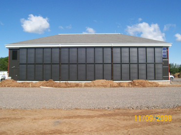
The vertical south-facing wall of the fire hall is covered with thirty four Thermo Dynamics G32 solar collectors (101 m2 gross collector area; 94 m2 aperture area). The solar collectors are the liquid-flat-plate type, with low-iron tempered glass glazing and Sunstrip absorber plate. The solar collectors are arranged in two arrays of twelve solar collectors, and one array of ten solar collectors. All three arrays are in parallel with each other. Within each twelve collector array, there are two sub-arrays of six solar collectors, each sub-array plumbed in series with the another. Within the ten collector array, there are two sub-arrays of five solar collectors, each sub-array plumbed in series with the another. The arrays are plumbed independently, and valved, to allow servicing of one array without shutting down the entire system.
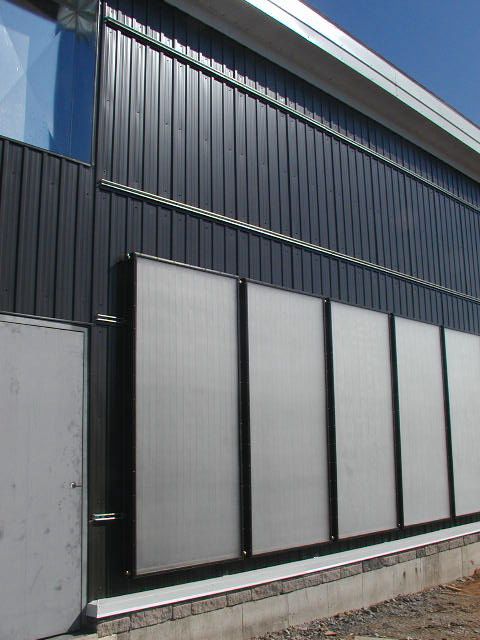
The solar collectors are mounted flush to the south wall of the building
in order to make an aesthetically pleasing solar wall. This also reduces
the magnitude of the wind loss coefficient as well as drastically reducing
snow collection which would decrease system performance.
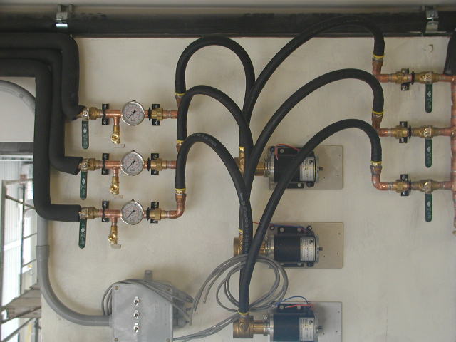
Each array is supplied with glycol via 3/4” nominal copper tubing. The hot solar return from each array is also 3/4”, eventually collected by 1.25” copper tubing and then supplied to two tube and shell heat exchangers. There are no external piping runs; all the distribution of glycol to/from the solar collectors is inside the building envelope. All piping is insulated with 0.5” thick insulation. The solar loop is fitted with pressure gauges, pressure relief valves and expansion tank to allow for the safe and efficient operation of the solar system
Solar Pumps™ and Photovoltaic Modules
The solar heat transfer fluid is a propylene glycol solution (40:60, glycol:water) and is circulated through the solar collectors by three TDL P118330 Solar Pumps™. One pump circulates the glycol in a single array of solar collectors. Each Solar Pump is powered by a BP Solar 30-Wpeak photovoltaic module. The PV modules are rated at 1.8 ampere. The PV modules are mounted on the south-facing vertical wall in the same plane as the solar collectors. The Thermo Dynamics Jolter™DT, a linear current booster with temperature sensing, is wired between each PV module and the permanent magnet DC motor that drives the pump. The Jolter™DT’s provide for pump start-up and continuous running at very low levels of solar radiation (approximately 100 W/m2). At full sun the PV modules produce a flow rate of over one liter per minute per solar collector.
Each Solar Pump is equipped with a high temperature shut off. When the
solar heat transfer fluid reaches 45°C going out to the solar collectors,
the pumps will shut off. If the supply temperature reaches 45°C,
then it would mean that the floor circulator is not activated and the
heat exchangers are not transferring the solar energy. This is a safety
shut off.
Solar Radiant Floor Heating System
The solar collectors are connected to two D4T28L12 DTL
Series Tube and Shell Heat Exchangers located in the mechanical room.
The heat exchangers
are connected in series on the shell and tube sides. The solar collectors
are connected to the shell side of the heat exchangers. The tube side
of the space heating heat exchangers is plumbed to the radiant floor
heating system.
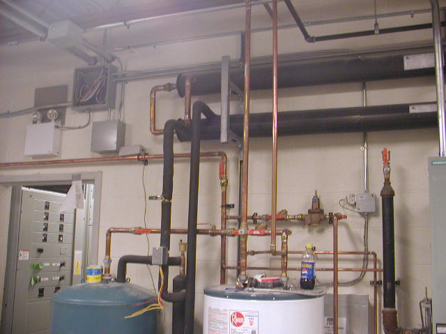
The heat exchangers are arranged so that counter flow operation is achieved.
Isolation, drain valves, and air vents have been installed to allow for
easy back flushing and maintenance on the heat exchangers.
Solar Domestic Hot Water
The solar collectors are connected to one D4T28L4
DTL Series Tube and Shell Heat Exchanger located in the mechanical
room.
This heat exchanger
is in parallel with the space heating heat exchanges. The solar collectors
are connected to the shell side of the heat exchanger. The water flows
through the tube side. The heat exchanger is installed vertically to
allow the water to thermosyphon into a 100 IG storage tank. A temperature
control with motorized valve has been installed to allow proper operation.
Solar system Major Component List:
• 34 – G32-P 4’ x 8’ Grid Solar Collectors (Thermo Dynamics
Ltd.)
• 3 - P118330 Solar Pumps™ (Thermo Dynamics Ltd.)
• 3 – PV30 Photovoltaic modules (BP Solar)
• 2 – D4T28L12 tube and Shell Heat Exchangers (Thermo Dynamics Ltd.)
• 1 – D4T28L4 Tube and Shell heat Exchanger (Thermo Dynamics Ltd.)
• 1 – TG454 Solar Storage tank, glass lined, 100 IG (Rheem)
Winter System Operation
The apparatus bay is to be maintained at 15°C.
The solar system will deliver energy to the apparatus bay when
ever available,
independent
of the thermostat. The thermostat will only control the operation of
the auxiliary electric heater.
The Solar Pumps are controlled by the PV panels. When there is sufficient
sunlight, approximately 100 W/m2, the pumps will begin to turn. The solar
heat transfer fluid will flow to the three heat exchangers. When the
temperature of the space heating heat exchangers reaches 80°F, the
radiant floor AC circulator will be activated and will allow the solar
energy to be transferred to the floor. This operation is independent
of the wall thermostat. At the same time, the solar heat transfer fluid
will flow through the domestic water heat exchanger causing the 100 IG
tank to increase in temperature. A thermostat controls this operation
and not allow the tank to exceed 55°C.
Summer System Operation
On a typical summer day the angles of incidence on the solar collectors are very high, ranging from 90° to a minimum of 65°. Therefore the maximum solar radiation incident on the solar collectors on a clear, sunny day would be 560 W/m2. However, due to the high optical losses associated with the high angles of incidence, the solar collector absorber will only see about 400 W/m2, at a maximum, and stagnation temperatures will be relatively low. The temperature rise of the solar collector absorber plate, given stagnation conditions, is ΔT = GT (ta)/UL = 400 W/m2/4.0 W/m2·K = 100°C. Therefore, there should be no problems associated with shutting down the solar loop in the summer when temperatures inside the building are above a satisfactory level.
Commissioning
The solar heating system was started up at the beginning of November 2008. On November 24, 2008 the site was visited for a final inspection and commissioning. The system is installed in accordance with good engineering practices. At the time of inspection, the all three Solar Pumps were operating and the solar collectors were under full sun.
The flow rate in the solar loop was measured 30 L/min. The three solar pumps were running at 17 VDC, and each was drawing from 1.60 to 1.69 amperes from the PV modules. The glycol temperature to the solar collectors was 20°C and the return temperature was 45°C. This represents a heat delivery rate of 48 kW. The outside ambient temperature was -5°C. It was a cold but a very sunny day. This is 1.4 kW per collector and is typical of this time of year.
View photographs of the installation
home | about us | solar collectors | solar systems | solar pumps | solar radiant floor heat |solar pool heat | solar fins | heat exchangers | project & photo gallery | technical specifications | downloads | product list | contact us
© 1996 - 2009, Thermo Dynamics Ltd.
All Rights Reserved
webmaster@thermo-dynamics.com
